Plan the placement of CIP equipment, pipelines, tie-ins, operating access, and maintenance zones before procurement or installation. A coordinated 3D model helps confirm that the proposed CIP solution fits the actual plant and can be installed, operated, cleaned, and serviced safely.
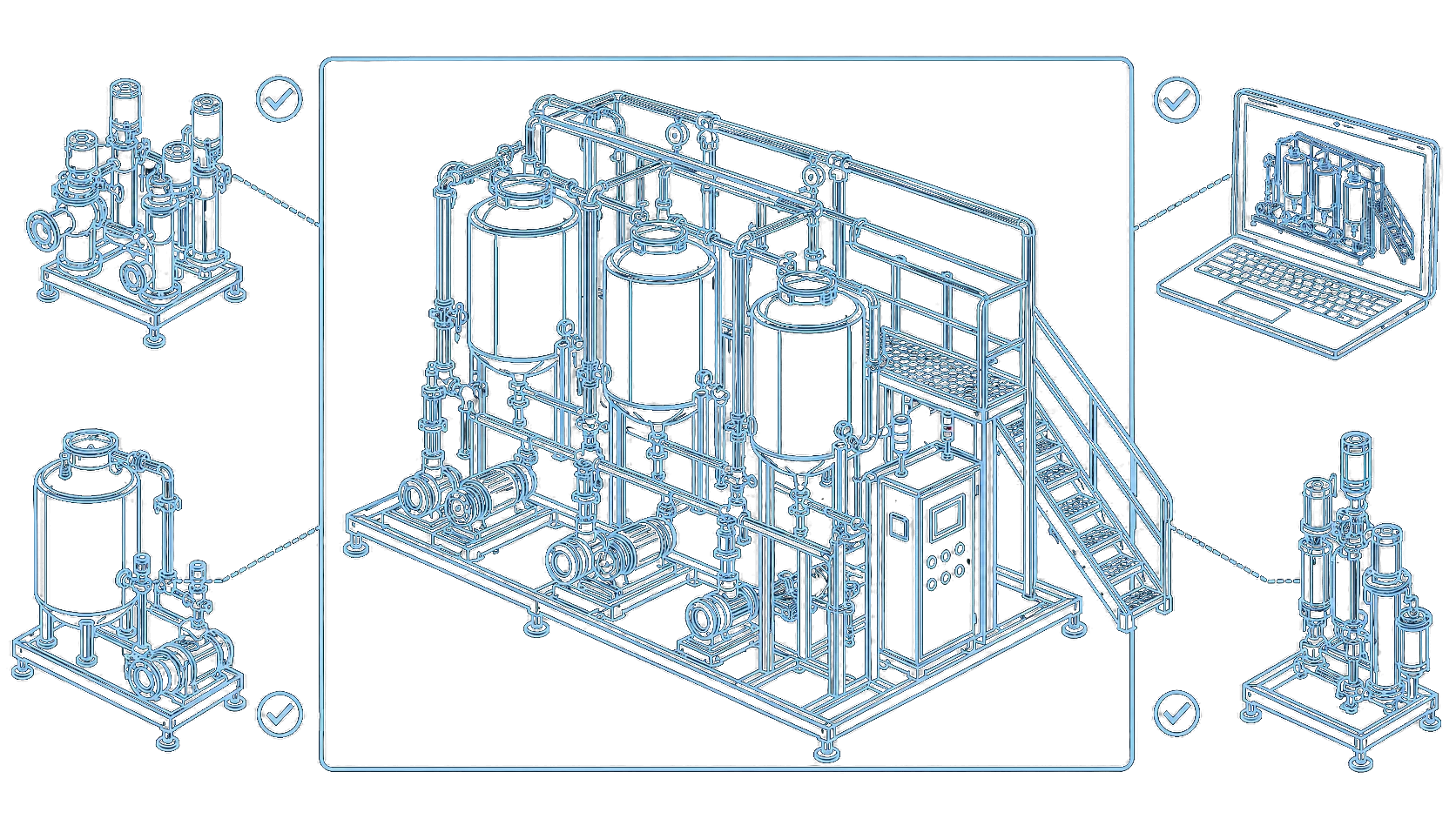

Verified equipment
placement
Coordinated pipe
routes
Maintenance access
review
Clash and tie-in
coordination
WHAT IS 3D MODELING & LAYOUT
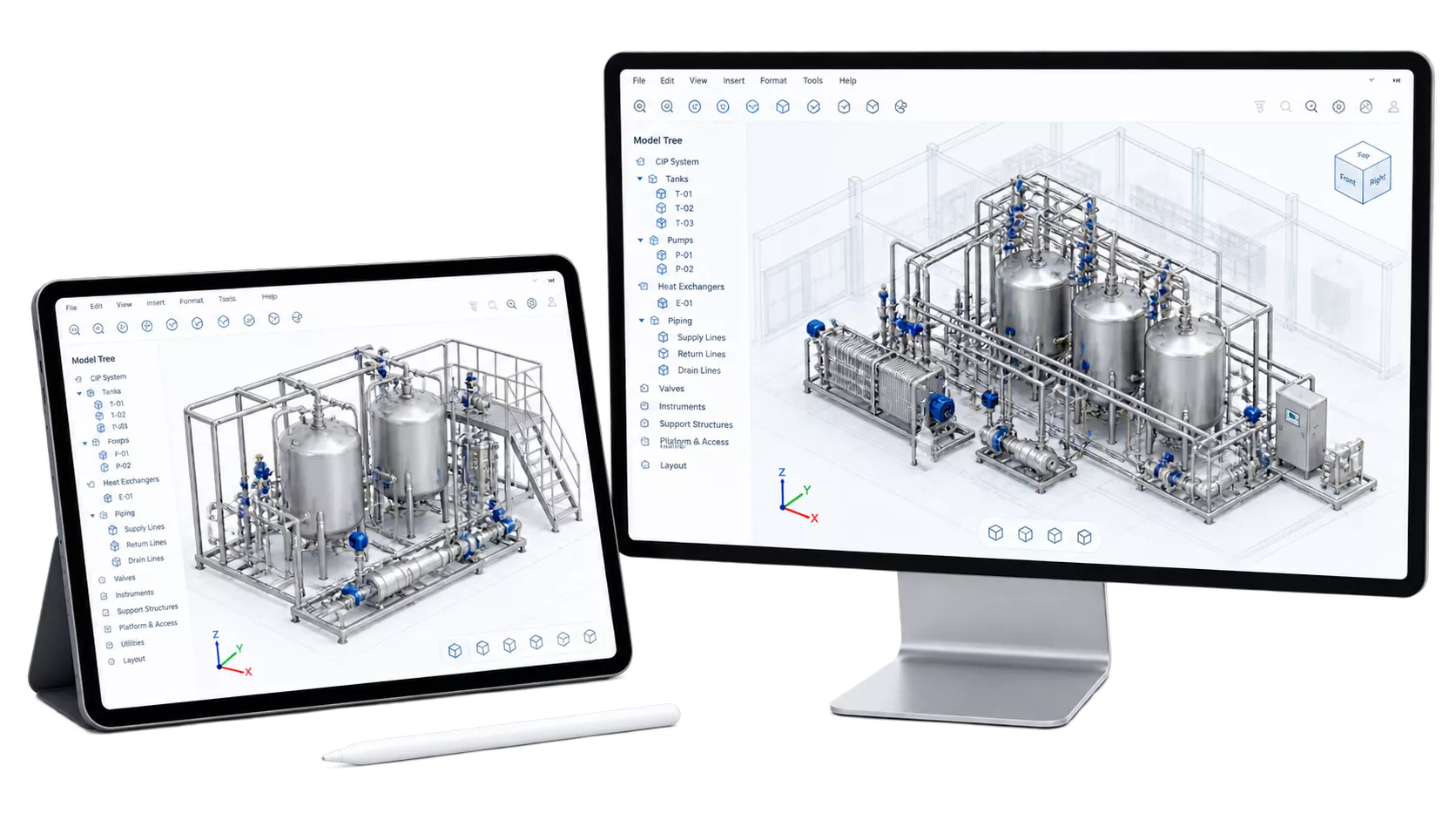
3D plant modeling combines scan data, existing drawings, vendor information, and engineering requirements into a coordinated CIP model. The scope integrates equipment layout design and 3D piping design for tanks, pumps, heat exchangers, dosing equipment, valve groups, pipe routes, access zones, and tie-ins. The resulting hygienic process layout provides a shared spatial reference before procurement and installation.
WHY LAYOUT ENGINEERING MATTERS
Even when process calculations and equipment selection are correct, the project may face problems if the skid does not fit, components cannot be serviced, pipes conflict with structures, drains are poorly positioned, or installation routes are blocked. Layout engineering identifies these risks before manufacture and installation.

Check equipment dimensions and positioning against the available space and surrounding plant geometry.

Identify spatial conflicts between the proposed CIP system, existing equipment, piping, and structures.

Review the clearances needed to inspect, service, and remove pumps, valves, instruments, and heat exchangers.

Plan access to controls, manual valves, sampling points, walkways, and routine working positions.

Align proposed connections with existing equipment and confirm the space needed for installation.

Review delivery, lifting, assembly, and routing constraints before equipment reaches the site.
WHEN THIS SERVICE IS NEEDED
Develop the layout when equipment placement, routing, or access could affect the CIP project. A coordinated spatial review supports decisions before procurement, manufacture, or site installation.
01
Define the equipment arrangement, main connections, and access zones before ordering or installing the station.
02
Coordinate new equipment and revised routes with the existing station and surrounding production systems.
03
Compare equipment footprints and routing options while preserving operating and maintenance space.
04
Check the proposed positions, revised connections, and delivery routes before moving equipment.
05
Develop routes around existing structures, utilities, and process equipment, with attention to drainage and access.
06
Compare layout options against footprint, pipe routing, service access, installation, and future expansion.
07
Review vendor dimensions and interfaces against the coordinated layout before manufacturing decisions are finalized.
MODEL SCOPE
The model brings equipment, piping, and the existing environment into one spatial reference. The included elements and routing detail are defined by the project requirements and agreed scope.
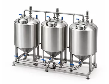
Tanks, pumps, heat exchangers, dosing systems, valves, and frames.
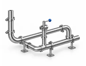
Supply, return, utility, drainage, and tie-in routes.
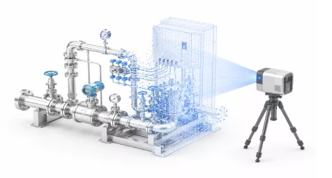
Equipment and structures represented from point clouds or drawings.
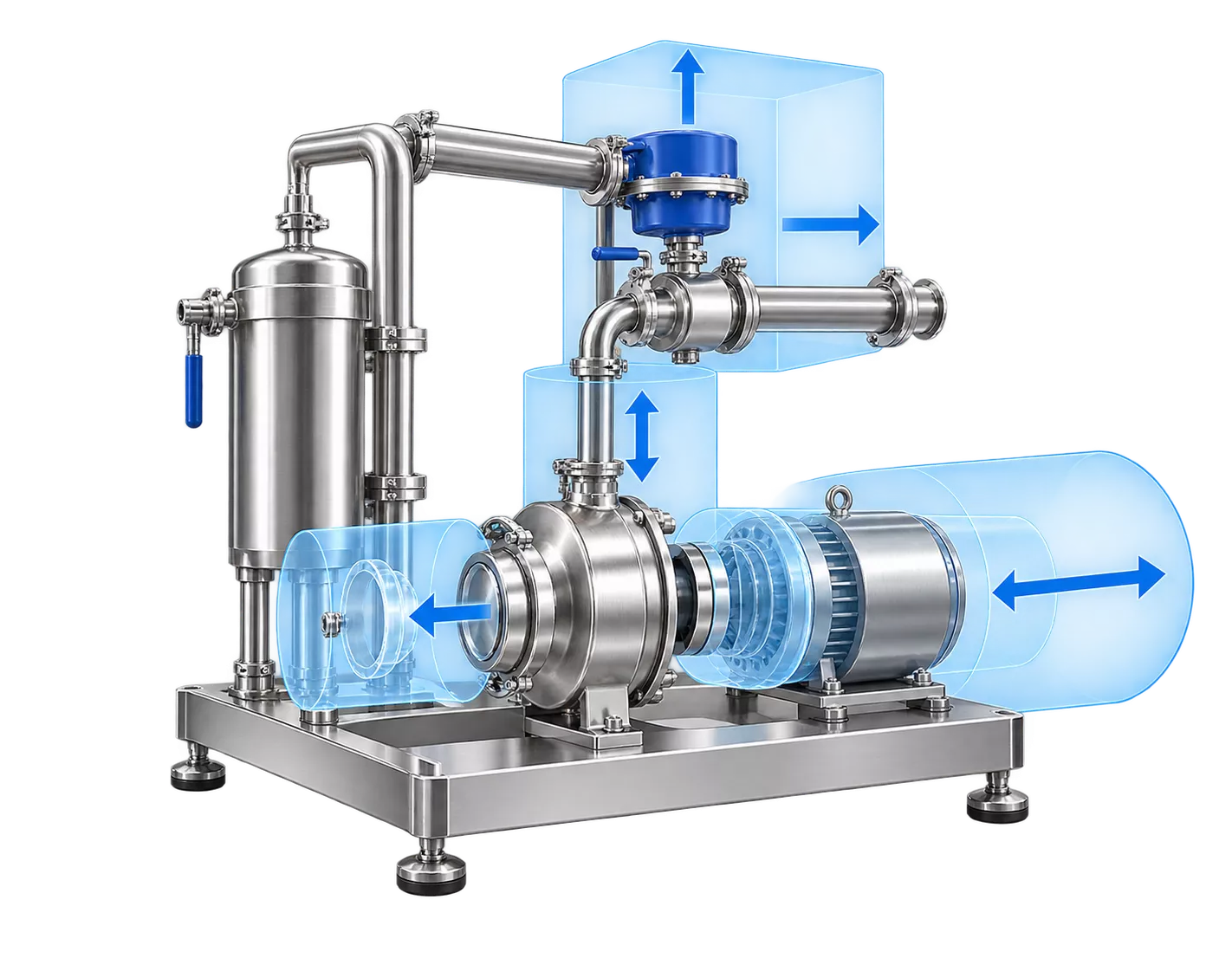
Clearance for service, component removal, and inspection.
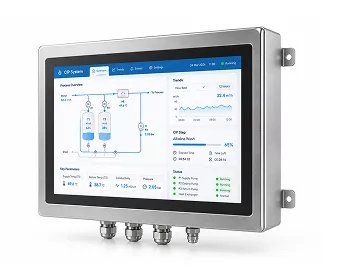
Access to HMI, manual valves, sampling points, and routine operating positions.
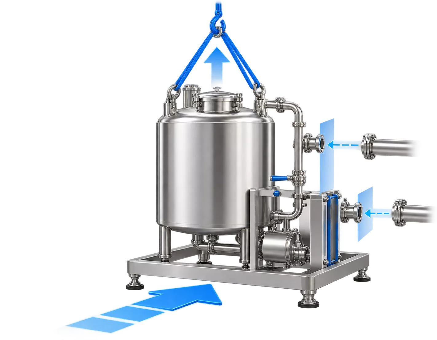
Space required for delivery, lifting, assembly, and connection.
HOW THE LAYOUT IS DEVELOPED
01
Review point-cloud data, equipment dimensions, vendor models, process requirements, tie-ins, and plant standards.
02
Place the main equipment according to process sequence, hygiene, operation, utilities, and access requirements.
03
Develop CIP, utility, and drainage routes and coordinate interfaces with existing systems.
04
Check spatial conflicts, service clearances, operator access, drainability, and installation constraints.
05
Review alternatives, document comments, and issue the approved model and layout views.
WHAT WE REVIEW
The review checks how the proposed arrangement supports installation, operation, and maintenance. Spatial findings are coordinated with process requirements, vendor data, and confirmed site conditions.

Check equipment footprints, heights, and required clearances against the confirmed room geometry.
Review proposed routes and branch arrangements for avoidable stagnant sections, with reference to the process design.
Check access for routine maintenance and the space needed to remove components using vendor requirements.
Review elevations, available fall, and drainage connections against the proposed routing and site constraints.
Coordinate connection positions, orientations, and elevations with the available site and equipment data.
Review walkways, working positions, and required clearances against the agreed plant access and safety requirements.
Check delivery openings, handling space, and assembly routes for the proposed equipment arrangement.
Identify modeled spatial conflicts and document the changes needed for coordination.
WHAT YOU GET
The model and layout views provide a shared spatial reference for engineering, procurement, and installation planning. Review comments document the coordination decisions and any items requiring further confirmation.

3D
VIEWS
CONC
PRC
REVIEW
COM
LAYOUT
NEXT ENGINEERING STEP
For brownfield projects, 3D scanning provides a reliable geometric basis before modeling begins. PFD and P&ID development can be coordinated with the model to align process logic, components, and spatial integration.
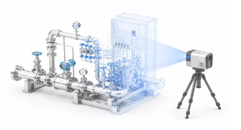
Capture the visible existing geometry to provide a measured reference for equipment placement, routing, and tie-in planning.
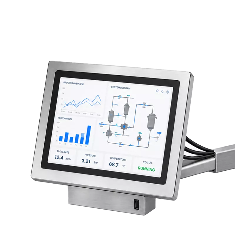
Define the main CIP flows, circuits, and operating relationships that guide equipment arrangement and routing.
Coordinate equipment, lines, valves, instruments, and connection requirements with the spatial model.
WHY CIP EXPERTS
01

We consider cleaning objects, supply and return paths, drainability, and cleaning-system interfaces.
02

We review equipment fit, cleanability, operation, and maintainability together.
03

Process, equipment, piping, automation, and plant constraints are considered together.
04

Viravix Engineering can support wider plant integration, installation coordination, and commissioning.
FAQ
Do you need a 3D scan first?
For existing plants, a scan is recommended when drawings are incomplete or dimensional accuracy is critical. Reliable existing CAD data may also be used.
Can vendor equipment models be included?
Yes. Vendor models can be integrated if they are available in a suitable format and level of detail.
Does the model include detailed piping?
It can, but the scope depends on the project stage. Concept routing and detailed routing are different deliverables.
Can several layout options be compared?
Yes. Alternative arrangements can be assessed against footprint, access, routing, installation, and future expansion.
Related Pages
Know exactly what happened in every cleaning cycle — temperature, flow, conductivity, and timing — for every zone in your dairy plant.

Share your scan data, drawings, equipment information, and project constraints. We will define the required model detail and coordination scope.
Thank you for your request!
Our team will contact you soon to discuss your project and the next steps.
Request Sent
Thank you for contacting CIP Experts. Our manager will contact you within one business day.
