Define the CIP process concept, cleaning circuits, main flows, heating, dosing, return logic, recovery, and drainage before detailed engineering and supplier quotation. A clear Process Flow Diagram gives every project participant one shared understanding of how the system should operate.
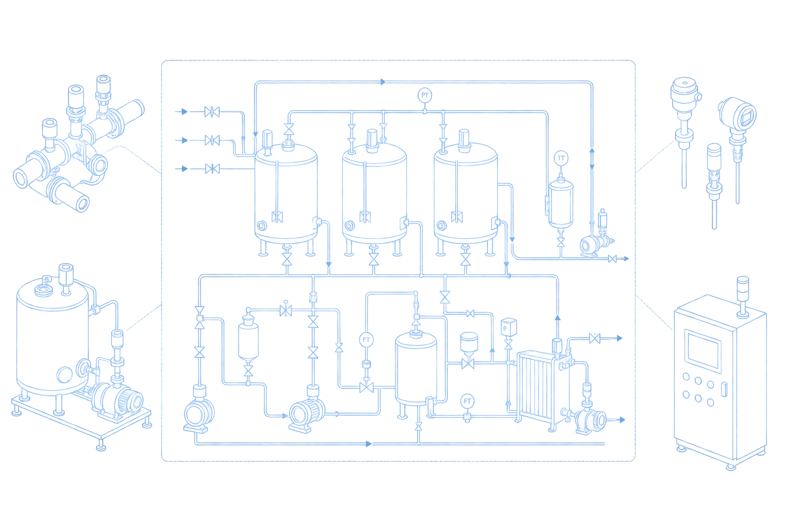

Shared process
understanding
Defined CIP
circuits
Clear operating
concept
Comparable supplier
proposals
WHAT IS A CIP PFD
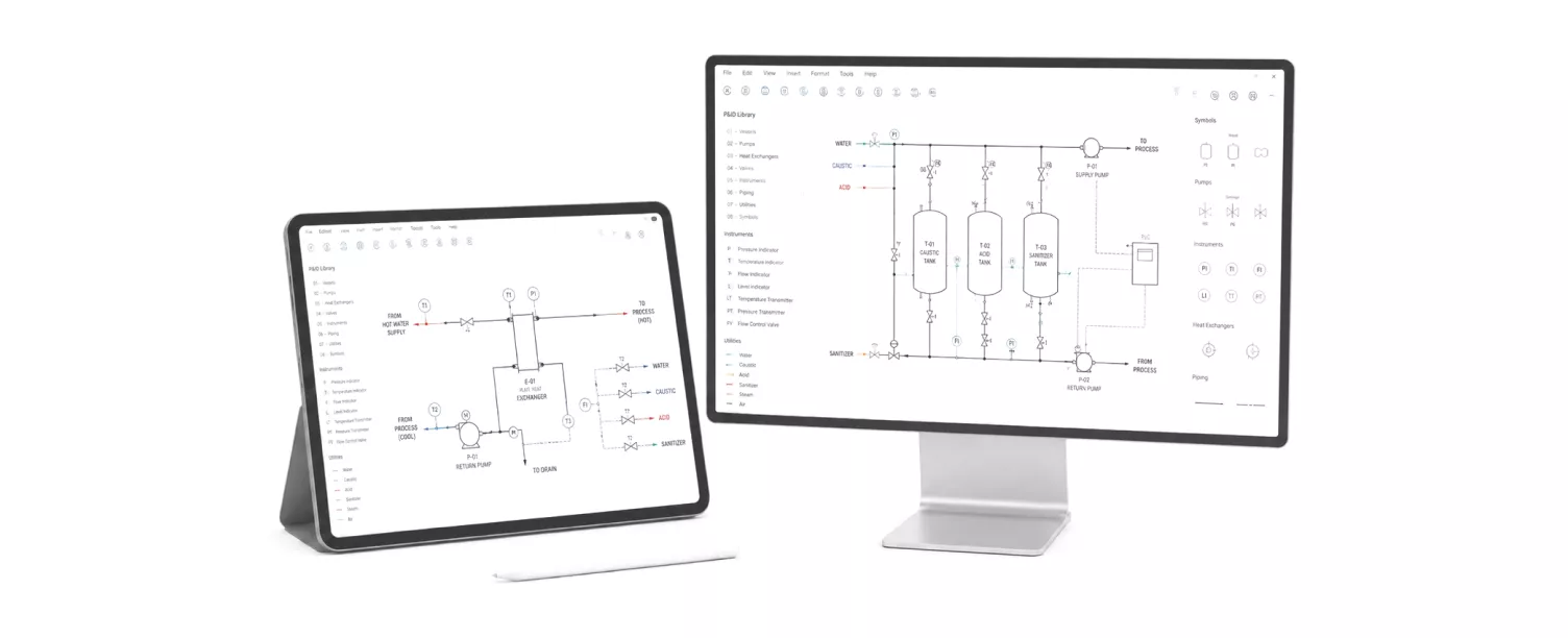
Our PFD development services for CIP systems in food plants create a CIP PFD showing the main equipment, cleaning objects, cleaning-media routes, process flows, utilities, and operating relationships at concept level. The process flow diagram establishes how cleaning should operate before detailed valves, instruments, signals, and connections are defined in the P&ID.
WHY PFD MATTERS
When the process concept is not documented, suppliers may propose different circuits, capacities, tank arrangements, recovery strategies, heating methods, or return logic. A clear PFD reduces conflicting assumptions and creates a consistent basis for P&ID development, RFQ preparation, equipment sizing, and technical comparison.

Engineering, production, quality, and suppliers work from one agreed view of how the CIP system should operate.

Cleaning objects are grouped into circuits with clear supply, return, and simultaneous-cleaning requirements.

Heating, dosing, circulation, rinsing, recovery, and drainage are connected in one process concept.

A common process basis helps suppliers prepare proposals against the same operating requirements and system boundaries.

Missing inputs, conflicting requirements, and utility constraints are identified before detailed engineering begins.

The agreed concept provides the starting point for equipment sizing, P&ID development, and control requirements.
WHEN THIS SERVICE IS NEEDED
The service applies when a new or modified CIP system needs an agreed process concept. It defines the main circuits, flows, and operating relationships before detailed engineering or supplier selection.
01
Define the cleaning scope, circuit arrangement, tank functions, and main flows before selecting equipment.
02
Review the current process concept and define changes to match updated cleaning and production requirements.
03
Determine how new cleaning objects connect to the station and affect supply, return, and capacity requirements.
04
Review circuit loads, cleaning frequency, and operating sequences against new products or production volumes.
05
Define which streams can be recovered, where they return, and how they are separated from discharge flows.
06
Reconstruct the process concept from available records and site information, recording any points that require verification.
07
Establish an agreed process basis so detailed engineering and supplier proposals follow the same requirements.
PFD CONTENT
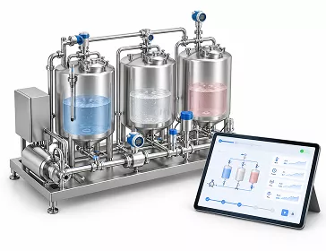
The PFD brings the main equipment, cleaning circuits, and media flows into one process overview. The level of detail depends on the project stage, available inputs, and agreed scope.
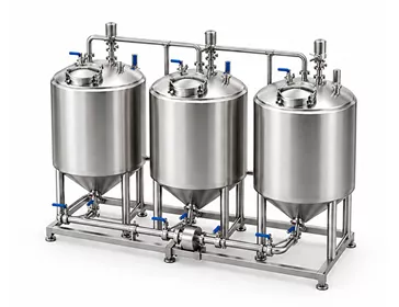
Tanks, pipelines, fillers, mixers, pasteurisers, and other CIP targets
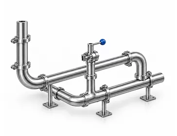
Grouping of washing objects and supply/return architecture
Water, alkaline solution, acid solution, disinfectant, and recovery streams
How cleaning media are prepared and controlled
Return destination, reuse, discharge, and phase separation
Main water, steam, compressed-air, chemical, and drainage interfaces
HOW THE PFD IS DEVELOPED
01
Review washing objects, products, soils, cleaning recipes, capacities, utilities, available documentation, and production constraints.
02
Define cleaning-object groups, main supply and return flows, tank functions, routing, recovery, and drainage.
03
Define the main cleaning stages, heating, dosing, circulation, rinsing, recovery, and sequence relationships.
04
Create or update the PFD and review it with engineering, production, quality, and automation stakeholders.
05
Document comments and issue the approved process diagram as the basis for the next engineering stage.
PROCESS DECISIONS
PFD development turns cleaning requirements into an agreed operating concept. Key decisions are documented, while unresolved inputs remain visible as assumptions or open points.

Define the cleaning objects assigned to each circuit and their main supply and return connections.
Identify concurrent cleaning needs and the capacity, routing, and production constraints that limit them.
Establish preliminary flow and capacity requirements from circuit demand and the planned cleaning schedule.
Define tank functions, heating methods, and chemical addition at the process-concept level.
Agree on recovery and discharge routes based on solution condition, contamination risks, and reuse requirements.
Define the basis for distinguishing return streams and directing them to recovery tanks or drainage.
Identify the main water, steam, compressed-air, chemical, and drainage connections needed by the concept.
Clarify where the CIP station connects to plant equipment and where each supplier’s scope begins and ends.
WHAT YOU GET
The PFD package gives engineering, production, quality, and procurement a shared process basis for the next project stage. It records the agreed concept, main interfaces, and assumptions that require confirmation during detailed design.

OBJ
STREAM
LOGIC
BNDRS
POINTS
DOC
RELATED ENGINEERING
Use the approved PFD as the starting point for detailed and spatial design. These services connect the process concept with component definition, existing plant geometry, and equipment layout.
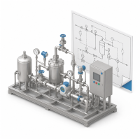
Translate the approved process concept into detailed equipment, piping, valves, instruments, and control interfaces.
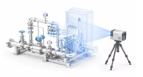
Capture existing plant geometry to support layout planning and identify spatial constraints around proposed connections.
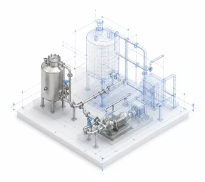
Develop the spatial arrangement of equipment and piping around the approved concept, available space, and access requirements.
WHY CIP EXPERTS
01

The process concept is connected to the equipment, soil, product, cleaning method, and required result.
02

Circuits and flows are developed around the actual production and plant constraints.
03

The approved concept can continue into P&ID, layout, automation, and tender documentation.
04

The PFD gives quality, production, engineering, automation, and procurement one common reference.
FAQ
What is the difference between a PFD and a P&ID?
A PFD shows the process concept and main flows. A P&ID shows detailed components, lines, valves, instruments, and controls.
Can you update an old PFD?
Yes. Existing diagrams can be reviewed against current equipment, circuits, operating logic, and project objectives.
Do you need detailed equipment data to start?
Concept development can begin with preliminary data, but assumptions and open points must be documented and later confirmed.
Can the PFD be used in a supplier RFQ?
Yes. It gives suppliers one process basis and helps make proposed solutions more comparable.
Related Pages
Know exactly what happened in every cleaning cycle — temperature, flow, conductivity, and timing — for every zone in your dairy plant.

Tell us what must be cleaned, the available production data, and whether the project involves a new station or modernisation. We will define the required process-development scope.
Thank you for your request!
Our team will contact you soon to discuss your project and the next steps.
Request Sent
Thank you for contacting CIP Experts. Our manager will contact you within one business day.
